27/10/09 Day 40

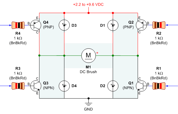
Finally, the H-bridge and motor session has come to an end, after successfully controlling motor speed and direction.

The follows are the 'bright' side of the project
1.H-bridge design from senior which only needed 4 transistor as compared to 6 from the previous post.
2. Got a 7809 voltage regulator to power the motor.
And I also have the 'DARK' side of it.
 green line -theoretical voltage value
blue- clockwise rotation
red -counter clockwise rotation
purple min- voltage for the motor to operate 1.5V
1. As what you can see the practical and theoretical value differ; practical and theory are 2 different thing!!
2. The motor should have 25 steps before reaching maximum as oppose to the practical 17 steps for CW and 14 for CCW.
" most probably caused by spike and false triggering"
3. Both voltages increase drastically at steps 3-4, passing the minimum operation voltage
" The motor just can't go at 1.5 voltage and sucks more voltage??"
4. I have problem with the max speed indicator in CCW direction.
***********************
Finally, I got the ADC working. My previous ADC ended up with a fried chip. One of the factor was that I didn't disable the digital input as told by the Atmel support team.
And now I finally found out what when wrong to my previous code.
 How silly of me... the computer does recognize (86
<170),>86 && ADCH<170)>
And now I finally found out what when wrong to my previous code.
 How silly of me... the computer does recognize (86
*********
UPDATES
new work place!! with an addition of a new all in one printer


UPDATES
new work place!! with an addition of a new all in one printer