Almost a month now, since the day I started learning AVR.
Currently having fun with dc motor.
As you've known, dc motor can rotate in counter clockwise and clockwise direction. To do that with a micro controller, you'll need to use a h bridge.
Whats a H-bridge? lets the pro tell you
1. robot room
2.rickeys world
3.chuck
last but not least
wikipedia H-bridge
the below schematic is taken from "robotroom' I followed it and it works well with 4 output pins.
then I try to reduce the no. of IO pin by connecting R2 with R1and R3 with R4.
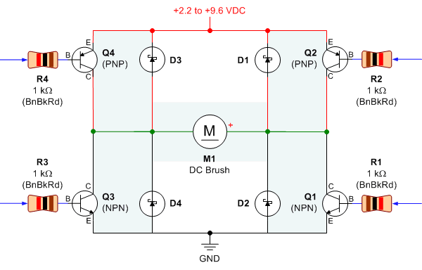 Then I try to reduce the no. of IO pin by connecting R2 with R1and R3 with R4, as seen in one website. Once turned on, the transistor went madly hot in no time.
I know there is a short somewhere, but where exactly? Well it took me sometime before I realize that by connecting the base of both transistor together, I was turning both of them Q1 n Q2, shorting the circuit!!
Solution to the problem?
I cracked my head, and finally got a simple solution! Just switch the position of the PNP and NPN transistor.

Yeah, I think someone thought f this solution a long time ago, and it must be in one of the website, but whatever it is , the motor is spinning now. Hooray!
*******
Ok the Hooray was just for able to make the motor spin, now I'm not delivering full power to the motor.
when supplied with 5v, the motor gets 3v, acceptable; with 9v, the motor stills receive 3v, thats not acceptable. So what went wrong? Might be the transistor not fully saturated.
when supplied with 5v, the motor gets 3v, acceptable; with 9v, the motor stills receive 3v, thats not acceptable. So what went wrong? Might be the transistor not fully saturated.
*******
Ok, after testing it, the transistor is fully on, with a voltage of 0.7 across the the emitter and base. Could it be the transistor? Well anyway wont going to investigate deeper into this manner for the moment, now I'll just stick this condition and will try to controlthe motor speed first.


No comments:
Post a Comment